Friday, April 30, 2010

Rear brakes


The rear brakes of all Beetles are drum brakes. The drums are secured to the axle by a large castellated nut torqued to 253 lb ft. This nut should be slackened before the car is raised from the ground. Select first or reverse gear and engage the handbrake, chock the rear wheels, remove the hub caps and the split pin from the
castellated nut. Then slacken off the nut, using a large square T drive (preferably a 'A in. drive), a strong 36 mm socket and a long pipe (the longer the better – a two metre pipe is ideal) to gain the necessary leverage to start the nut. If the nut stays stuck fast and the car moves when you apply pressure, try jacking one side of the car up at a time, removing the roadwheel and chaining a (spare) wheelnut to the chassis. If all else fails, soak the nut in freeing solution or try applying gentle heat to make the nut expand.
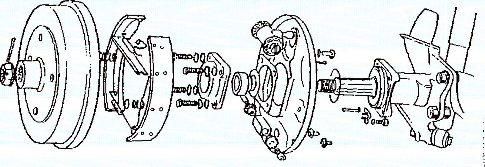
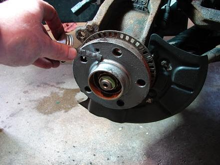
When both axle nuts have been loosened, slacken the rear wheel nuts, engage the steering lock (wheels dead ahead), chock the front wheels, raise the rear of the car and support it on axle stands. Disengage the hand brake. Remove the axle nuts. Slacken off the brake adjusters until the drum turns freely (see Chapter 3). and pull the drums from the splined axle shafts, tapping the drums with a rawhide mallet to centre the shoes or even using a puller if necessary. Some brake shoes contain dangerous asbestos, so don a dust mask and gently wipe the drum and the shoes clean out of doors. If there is less than 0.1 in. of frictional material left on the brake shoes then they will have to be renewed. If a brake drum is scored internally then it should be replaced.
To strip the brakes, use a pair of pliers to remove the shoe retaining springs and their clips. Ease the lower ends of each shoe out from the slot in the adjuster tappet, and then ease the top ends out of the wheel cylinder tappets. Ease out the handbrake cable end and remove the shoe/spring assembly.
Examine the wheel cylinder hoots and brake backplate for signs of brake fluid leakage: if this is suspected, then a wheel cylinder kit, comprising new piston (tappet) seals and boots should be obtained and titled. Clamp off the length of flexible brake hose before removing the wheel cylinder, and bleed the system afterwards. Check that both tappets are free to move and, if they are seized, try using a large screwdriver through the jaws to turn and free them don't force too hard or you will spread the jaws. On really stubborn wheel cylinders which are completely seized the last resort is to remove them from the car, drain all brake fluid from them and then use heat to free the tappets: the heat destroys the tappet seals, which must be renewed. Examine the wheel cylinder bore for damage, and renew if necessary.The hub oil seal can also teak with the result that the brake backplate becomes covered with fluid, but in this case, the fluid will obviously be oil. Because you will normally discover a leaking hub oil seal when you are working on the brakes, a brief description of the necessary work is included here.
Either drain the transaxle of oil, or jack up the side of the car being worked on so that the hub is at a higher level than the transaxle. Unbolt the four hub cover bolts, then pull the cover from the backplate, having placed a suitable receptacle underneath the catch any escaping oil. Remove the old oil seal, the spacer, the '0' rings from the casing and axle, the gaskets either side of the brake backplate, and clean all components. Use a block of wood to drive the new oil seal into position — not forgetting to replace the washer first. Fit the axle '0' ring. spacer and the '0' ring in the cover. Pull the backplate gently forwards until you can gently feed the inner gasket through the hole in the centre of the backplate and into position, fit the front gasket, and carefully reassemble, taking care not to damage either of the gaskets as the bolts are passed back through. Torque the bolts to the recommended level then, with the car back on its wheels or only slightly raised to allow access to the transaxle filler plug on the nearside. top of the transaxle oil.

The rear brake assembly. (Courtesy Autadata)

Bleeding the brakes


If the brake pedal feels soft and spongy, then there is air within the system. Unlike brake fluid, air can be compressed, and the soft feel of the pedal is due to the fact that pushing it is compressing air rather than pushing non-compressible fluid to operate the brakes. In this case, the brakes have to be bled. The brakes also have to be hied after any part Of the hydraulic system
has been temporarily disconnected.Bleeding the brakes entails pumping fluid through the pipes until the fluid which contains air bubbles is removed from the system via one of the bleed valve nipples. The nipple is turned to allow fluid to escape as the pedal is pumped, then tightened before the pedal returns. To prevent air from re-entering the system via the bleed nipple, a short length of transparent plastic pipe is attached to it and the other end is immersed in a container of clean brake fluid.
If you have to bleed the whole system, begin with the wheel furthest from the master cylinder and work forwards (single circuit) or, in the case of dual circuit systems (in which you'll have a tandem master cylinder and front and rear brakes with individual circuits) bleed nearside front, offside front, nearside rear and finally offside rear.
To bleed a brake you will require an assistant to push the brake pedal for you. Attach the pipe to the brake nipple and immerse the other end of this in a small container of clean brake fluid. Open the nipple by turning it and call for the brake pedal to be depressed and held down. When your assistant has done this, tighten the nipple, and then ask your assistant to release the pedal. Repeat the exercise until clear fluid with no air bubbles can be seen coming from the nipple. Ensure throughout this operation that the level of the fluid in the master cylinder is correctly maintained.
Sometimes air can become lodged somewhere in the system and refuse to be bled in the normal manner. If this happens the pedal will feel spongy. The air can usually be dislodged by going through the motions of bleeding the brakes, but ask your assistant to let his or her foot slide off the brake pedal so that it returns sharply. A good brake pedal is nice and solid, and has not too much void travel, so that if one circuit fails (tandem master cylinder) then the other will still operate. If the pedal travel is too great, check firstly that the rear drum brakes arc correctly adjusted, then adjust if necessary the master cylinder push rod. if the rear brakes are not correctly adjusted –and even one shoe out of
adjustment will cause this – then the pedal will travel some distance as the shoe(s) concerned is moved by the pedal. You can usually hear a sound as the shoe moves and contacts the brake drum when this happens.
You don't necessarily have to jack up the rear of the car to adjust the handbrake; it is possible to reach the adjuster holes by lying on the ground at the rear of the car (watch out for the hot exhaust!). (Remember the advice given in Chapter Three about using a nut and bolt to remind you of which way to turn each adjuster.) It is very easy to become confused and to wind an adjuster fully in. and to believe that it is fully out! in addition to the extra brake pedal travel which will highlight the error, the handbrake lever will also possess far too much travel.
Brake bleeding is one of those activities which goes without a hitch nine times nut of ten – on the tenth occasion, it can be frustrating when you are unable to obtain a good solid feel to the pedal. The tenth occasion usually follows a full restoration, when you are racing against time to get the car ready for the scheduled MOT test. Don't carry on feeding good brake fluid through the system; it's expensive and should never be re-used. Try using a brake hose clamp (or two on front then rear, in the case of dual-circuit systems) on each flexible hose in turn, and feel whether this makes any difference to the pedal. The chances are that when one particular hose is clamped, the pedal suddenly behaves perfectly, showing you which wheel cylinder or calliper still has air inside.
If, after all your attempts to bleed the system, the pedal is soft, then get a second opinion from an experienced mechanic. The chances are that the master cylinder needs attention in the form of new seals, although dirt in the system. persistent air bubbles, One-man brake bleeding kits, which are fitted with a small non-return valve to prevent air from being sucked back into the system, are available. The author has tried various of these and found that, while some work
satisfactorily, some of the cheaper kits give problems with the non-return valve. As ever, you are tdvised to buy the very best tools which you can afford.

BRAKES


Beetles manufactured prior to May of 1950 had mechanically operated brakes; all Beetles made from that date have hydraulic braking systems. Because of the comparative rarity of pre-] 950s cars, this book covers only hydraulic systems. Owners of Beetles with mechanical brakes will find the details they need in the specialised workshop manuals dealing with early Beetles.
In essence the Beetle, in common with most cars, has two separate brake operating mechanisms. The handbrake is operated mechanically and acts only on the rear wheels whilst the footbrake acts on all four wheels using hydraulic pressure. When the brake pedal is depressed, a piston moves within a cylinder (the master cylinder) which contains non-compressible brake fluid. Because this liquid cannot be compressed, this action pushes it Acing a series of pipes and hoses to smaller cylinders containing pistons (the wheel cylinders and pistons in the case of drum brakes and the callipers and pistons for disc brakes), so placing pressure against the secondary piston and causing it to move.
The secondary pistons press shoes (drum brakes) or pads (disc brakes) against the drum or disc respectively; these are mechanically fastened to the rotating road wheels. The friction between shoe/dr4un pad/disc causes the road wheel's speed of rotation to slow, so slowing and stopping the car.
If you are undertaking a bodyshell-off restoration, then unless the brake pipes have obviously been recently replaced (and are not kinked). it is worth renewing them whilst accts is good. if you intend keeping the car for any great length of time then consider fitting the more expensive nickel-copper alloy brake pipes, which should last as long as the car. Because it is highly likely that most people who are restoring a Beetle will wish to completely overhaul the braking system, this entire section is devoted to a full brakes overhaul.
It is important to stress that when working with the braking system. cleanliness is vital: keep all lubricants well away from discs, drums, shoes and pads, and do not allow the brake fluid to become contaminated.

Gearbox


The Beetle gearbox is very long-lived provided that it is not abused. In time, though, even this robust unit can develop annoying noises when under way. Gearbox noises do not necessarily indicate serious problems, and many people learn to live with them as long as they don't become too loudl A noisy gearbox can last for years. Some gearbox problems, however, are more terminal and, after you have gone to the trouble of restoring your Beetle, it would be heartbreaking to have to remove the engine and transaxle because of some developing fault. Stripping, inspecting and rebuilding a gearbox is no task for a novice, and there are some convincing arguments for opting instead for a complete exchange reconditioned unit.
The individual gears in a gearbox mesh with the laygear cluster, and excess or uneven wear in just one gear in time wears the laygear teeth out of true. If you replace a noisy (damaged) gear, then you should really also replace the laygear cluster because this meshes and has worn with it, which means replacing all of the other gears as well, because the laygear teeth wilt have worn in concert with the teeth of each of the gears! In short, a complete rebuild using all-new components is required, which is always more expensive (assuming that you can obtain the components) than an exchange reconditioned unit. The lower cost alternative is to fit another gearbox salvaged from a scrap Beetle. Buying such a unit privately from a classified advertisTent is risky, buying from a general breaker's gives a guarantee of replacement if the 'box turns out to be faulty: the best option is buy to from a specialist Beetle restorer or breaker.
Whilst replacing the gearbox, consideration should be given to fitting urethane axle gaiters and a urethane gearshift coupling. These are more robust and long-lived than the original rubber items. The starter motor support bush is located in the transaxle casing and, if worn, the starter can become at first noisy and later it may jam. Offer the starter front spigot into this bush and feel for excess play. It may prove necessary to replace the bush – work best undertaken by an automotive engineer. The differential shares the transaxle housing with the gear assembly and again it is recommended that any problems be dealt with by a transmission specialist: These businesses can be found in many large towns and, although some will refuse to work on the Beetle transaxle, the better ones will be happy to inspect your transaxle and undertake any necessary repairs. When you come to box up your Beetle, pay especial attention to the condition of the plate which sits on the spine around the gearshift lever aperture. The two folded protrusions must point upwards and the pressing must be replaced if these are worn. One of the two lugs prevents the driver from shifting into reverse unless the lever is pressed firmly downwards: when the lugs arc worn it is ail too easy when changing down from third gear to inadvertently go straight across the gate to reverse – not only embarrassing but also hard on the gear teeth!


The diagonal arm suspension type transaxk mountings. Don't _forget to remove the clutch cable. (Courtesy dutodaia)

Double-jointed drive axle cars


Check firstly the fixings used on the inner drive shaft CV flanges, and if necessary obtain the correct tool for their removal from a specialist Beetle spares supplier.
Remove the oval cover plate at the rear top of the spine chassis, and remove the 8 mm square selector rod coupling bolt, which may be wired. Chock the front wheels, raise the rear of the car and support on axle stands. From underneath the car, undo the drive shaft inner CV joint fixings both sides of the car, using the appropriate tool. It usually pays to clean out Allen heads and splined fixings beforehand. Slacken the clutch lever cable wing nut until it can be unhooked, and remove the two nuts on the transaxle side cover which hold clutch cable clamps to free the cable from the transaxle.
Remove the earth strap from the transaxle casing, then undo the single nut which now holds the starter motor, and remove the starter motor. Check that nothing is left which connects the transaxle to the chassis legs.
Support the transaxle. Slacken the two front mounting bolts (nearest the front of the car) and remove the two main bolts. The gearbox can be withdrawn from the car or lowered onto the chassis legs until you are ready to manoeuvre it out.
Refitting is the reverse of removal: be sure to check the transmission oil level and top up if necessary.

Swing axle cars


The transaxle must be removed complete with axle tubes. The job is much more complicated and long­winded than on later cars, and so careful consideration should be given whether to replace the gearbox with a reconditioned unit as a matter of course during a full restoration, when the car will be stripped down completely and the task can be accomplished more easily while the bodyshell is off the chassis.
Chock the front wheels, apply the handbrake and place the car in gear, then remove the hub caps and slacken the hub nuts using preferably a burst-proof hexagonal socket and a very long lever! Slacken the wheel bolts. Disengage the handbrake and select neutral gear. Remove the oval cover plate at the rear top of the spine chassis, and remove the 8 mm square sel5ptor rod coupling bolt, which may be wired, then raise the rear of the car and support it on axle stands.
Remove the roadwheels and the hub nuts. Slacken the brake adjusters and remove the drums. then strip the brake components (as detailed in the section headed 'Brakes'), using clamps on the lengths of flexible hose to cut leakage of fluid.
Slacken the clutch cable nut and disconnect it from the clutch operating arm.
Use a sharp chisel or centre punch to make a mark on the trailing arm next to the mark on the hub casing to allow accurate rebuilding, then unbolt the hub from the trailing arm and pull the axle shaft away. Undo the lower damper nut and bnit and pull this away from the hub casing. Support the transaxle and remove the four nuts at the front, followed by the two large nuts at the rear. The transaxle, axle shafts and hub assemblies can now be pulled rearwards and lowered.
When re-fitting. offer and bolt the transaAe into position before tackling the axle shafts. Ensure that the mark which you made on the trailing arm aligns with the hub casing mark, otherwise, the rear tracking will be out, causing accelerated tyre wear and adversely affecting road-holding. There is a special tool which clamps to the torsion tube and to the swing axle shaft to correctly position the latter. If you are unsure that the spring plate is correctly positioned, then take the car to a VAG workshop or Beetle specialist and have the job done properly.

Gearbox (transaxle] removal and refitting


The gearbox and differential share the same housing. and the complete assembly is called a transaxle. The transaxle cannot be removed until the engine has been taken out, and the swing axle and double jointed drive shaft Beetles each have their own routines, and are covered separately. Because the engine will have been removed before the transaxle, it is assumed that normal safety precautions especially battery disconnections — have already been taken. It is advisable to clean and
Removing or re-fitting a gearbox has a fun factor on a one to ten scale of nought! There is no real alternative to lying on your back and wrestling with the thing, which makes your arms ache if as is normal, the gearbox decides to be awkward. apply penetrating oil to all fixings which will have to be undone some time before starting work. so that the oil has plenty of opportunity to do its job. '

Clutch removal


With the engine removed from the car, lock the flywheel using a large screwdriver wedged against the flywheel teeth and the starter motor aperture. Loosen the clutch bolts evenly in a diagonal pattern to avoid causing distortion of the pressure plate. Release the pressure from the springs slowly until the clutch comes free.
Examine the driven plate frictional material. If this has worn down so that it is close to the rivet heads then replace the plate. if it shows contamination (oil) then replace it and ascertain whether the oil has come from a leaking crankshaft seal or gearbox input shaft seal and replace the leaking seal before reassembling the clutch. If the driven plate shows signs of burning then renew it and ensure that in future the clutch is correctly adjusted and not slipping.
If the driven plate rivets have become exposed then they can severely score the flywheel and pressure plate, in which case the affected components should be replaced, although minor scoring of the flywheel may be turned off; check with an automotive engineer.
Check the condition of the diaphragm or coil springs and replace the pressure plate assembly if wear or damage are apparent.
When re-fitting the clutch, it is important that the driven plate is gripped exactly in line with the gearbox input shaft, otherwise, the plate could be damaged during engine re-fitting. There are many clutch alignment tools available for this purpose; they hold the driven plate in line with the other components whilst the pressure plate is bolted tight. Some people use a spare input shaft to achieve this: others can assemble the clutch accurately by eye.

CLUTCH/GEARBOX


The clutch is a very simple mechanism. The driven plate has frictional material on its surfaces and is located on the gearbox input shaft splines so that, when it turns, the input shaft also turns. The driven plate is normally gripped tightly in a sandwich between the flywheel and the pressure plate (the latter contained within the clutch cover, and the pressure provided either by diaphragm or coil springs, depending on the type of clutch), so that when the engine turns over, the clutch assembly and hence the driven plate and gearbox input shaft also turn.
When the clutch pedal is pressed downwards, the clutch operating lever moves the release bearing which in turn pulls the pressure plate away from the driven plate, so releasing the driven plate from the sandwich between the pressure plate and flywheel and
disengaging drive to the gearbox.
During the course of a restoration it is as well to replace the clutch as a matter of course unless it is in very good condition. If the clutch in daily use develops problems such as a failure to disengage. dragging or slipping then try adjusting it via the large wing nut on the clutch operating lever before removing the engine!

Running in


Before starting up a rebuilt engine, the author strongly recommends that the spark plugs are removed and the engine turned over for perhaps twenty or thirty seconds using the starter motor – it will spin quite quickly without the spark plugs and hence compression. This allows the oil pump to get oil moving in the all-important mains and big end bearings before those components are subjected to the stresses which occur when the engine fires up.
A rebuilt engine does, contrary to popular myth. benefit from being given a 'running-in' period – that is, a period of use on the road when revolutions are restricted to perhaps 3,500 rpm and the engine is not allowed to labour in too high a gear. In other words, drive slowly and be gentle with a rebuilt engine.
•ato Ity
rte ifThe new and the machined engine components in a rebuilt engine will all appear to fit very closely with their neighbouring components, but they still have to be finally 'bedded in' by being run in the assembled engine. During this bedding-in period, wear of components (journats,crankpins, bearings, piston rings and cylinders etc.) is initially very high, but the rate of wear progressively reduces.
Before putting the car on the road the author strongly recommends that you run the engine for perhaps ten minutes at around 1,500 rpm and a further ten minutes at 2.000 rpm – then change the engine oil and clean the filter. These running periods can be increased and indeed many authorities will advise that both the periods and the revolutions are increased. The idea of this is to start bedding the engine components in before the extra stresses of feeding power through the wheels is brought to bear, especially on the mains and big end bearings.
Remember that component wear is also always higher when the engine is cold, so take it very easy on the road for the first few miles each day. If your daily journey begins with a long uphill climb then warm the engine through before tackling this!
The author would personally recommend that for the first 500 miles on a rebuilt engine you limit top then the generator pedestal, inlet manifold and carburettor, oil cooler and finally the generator and fan shroud.
You can test run the engine on the floor if desired and if you can obtain an early transaxle half casing complete with starter motor. However, few enthusiasts will possess this, and so they have to refit the engine and hope for the best!
Running in
Before starting up a rebuilt engine, the author strongly recommends that the spark plugs are removed and the engine turned over for perhaps twenty or thirty seconds using the starter motor – it will spin quite quickly without the spark plugs and hence compression. This allows the oil pump to get oil moving in the all-important mains and big end bearings before those components are subjected to the stresses which occur when the engine fires up.
A rebuilt engine does, contrary to popular myth. benefit from being given a 'running-in' period – that is, a period of use on the road when revolutions are restricted to perhaps 3,500 rpm and the engine is not allowed to labour in too high a gear. In other words, drive slowly and be gentle with a rebuilt engine.
•ato Ity
rte ifThe new and the machined engine components in a rebuilt engine will all appear to fit very closely with their neighbouring components, but they still have to be finally 'bedded in' by being run in the assembled engine. During this bedding-in period, wear of components (journats,crankpins, bearings, piston rings and cylinders etc.) is initially very high, but the rate of wear progressively reduces.
Before putting the car on the road the author strongly recommends that you run the engine for perhaps ten minutes at around 1,500 rpm and a further ten minutes at 2.000 rpm – then change the engine oil and clean the filter. These running periods can be increased and indeed many authorities will advise that both the periods and the revolutions are increased. The idea of this is to start bedding the engine components in before the extra stresses of feeding power through the wheels is brought to bear, especially on the mains and big end bearings.
Remember that component wear is also always higher when the engine is cold, so take it very easy on the road for the first few miles each day. If your daily journey begins with a long uphill climb then warm the engine through before tackling this!
The author would personally recommend that for the first 500 miles on a rebuilt engine you limit top
speed to around 50 mph, that you accelerate as slowly as possible and that you tackle steep hills – if at all – in a suitably low gear. He would at that stage be inclined to change the engine oil and clean the filter to get rid of any tiny fragments of metal which the oil should have cleaned from bedding-in new components. During the second 500 miles he would recommend a revolutions limit of perhaps 4,000 rpm, terminating again in an oil change and fitter clean. The next two 500 mile intervals should be marked with oil changes if you want your rebuilt engine to enjoy the longest possible life and, when you've gone to the trouble of restoring your car, who wouldn't?
Remember that during the running-in period, you are effectively 'blueprinting' some of the most important and stressed components in the engine. An engine which is abused during this period will inevitably last less long and wilt usually give less power and use more fuel than one which is run in correctly. However, don't be so single-minded during the running-in stage that you present a danger to other road users – if you crawl along the motorway at 35 mph then you will present a danger both to other road users and to yourself: avoid such roads until your engine is run in.

PISTON AND CYLINDERS


It is taken as read that you have had the pistons, piston rings and cylinders examined for damage, measured for wear or to ensure they have not become oval, and perhaps the pistons weighed by an automotive engineer and everything machined or renewed as appropriate.
Fit new cylinder gaskets to the crankcase halves. You can fit the pistons alone and the cylinders afterwards, or the pistons with the cylinders already attached as long as the gudgeon pin hole is clearly visible. Lubricate each bore with a little engine oil, then use a ring compressor to fit the pistons into their respective cylinders. Offer the pistons into position on the small ends – ensuring that the arrows stamped into the crown face the flywheel – then gently press home the gudgeon pins and fit the circlips. Use oil to lubricate the cylinder seals before pushing the cylinders fully home.
Cylinder head refit
Pull the push rod tubes to stretch them to a fraction over seven inches, and fit new sealing rings. Slide the cylinder head onto the studs and position the push rod tubes (seam upwards) before pushing the cylinder head fully home. Check that the push rod tubes are correctly located, and torque the cylinder head nuts in the correct progressive sequence. Fit the pushrods then the valve gear.

The cylinder head is the one part of the engine which commonly requires attention that is within the abilities of most DIY enthusiasts. Although it is still recommended that an automotive engineer inspect them in the course of a full restoration, normal mechanical repairs are another matter, and are covered here.
Clean all carbon from the cylinder head, using the correct tool and not an old screwdriver, the sharp edges of which are guaranteed to dig into the head, causing damage. Proprietary cleaning fluids such as Autoline Gasket Remover can help remove stubborn carbon deposits.
Examine the head for cracks between the valve seats or a valve seat and the spark plug hole. Check for signs of exhaust seat/valve burning. If any cracks are found then the author recommends the parts be taken to an automotive engineer or replaced/exchanged. if everything seems in order, it is worth lapping in the valves.
Uneven wear in the valve seats can result in poor sealing qualities and, if the damage is not too bad, the valves may be lapped in. It is worth while doing this as a matter of course whenever the heads have to be removed. You need grinding paste and a tool which is no more than a wooden stick with a sucker on the end — both are widely available and cost very little. Simply, the valve is placed in its guide, its mating edge is coated with grinding paste (coarse first, followed by fine), the rubber sucker attached to the valve and rotated to and fro between the hands. Every few seconds, stop, lift and turn the valve through 60 degrees and start again. inspect the valve and its seat periodically, and when you can see an unbroken matt line around both switch to the fine paste and repeat the process. When the valve and seat are perfect, the valve will bounce when dropped into its seat from a height of perhaps two inches.
Check for excess wear in the valve stems/guides by inserting a valve into its stem from the outside of the head and feeling for sideways movement. If this is found then new valve guides and valves should be fitted; although this can be undertaken at home it is recommended that the work is entrusted to an experienced professional.

Rebuild continued
Replace the fuel pump push rod assembly and the pump. and refit the distributor drive shaft: when fitting the thrust washers, use grease to hold them together and fit them with a thin length of rod to ensure that they don't drop down into the crankcase! Note the attitude of the drive shaft slot in the illustration.
Refit the oil pressure relief valve (two on cars after 1969) and the oil strainer and its cover plate. Check the flywheel ring gear teeth for damage, replace the gasket and offer the flywheel into position, remembering to line up the dowel and hole which you marked when stripping the assembly. Refit the crankshaft pulley and the flywheel. torquing the former to 33 ft lbs and the latter to 253 ft lbs — OK, let's be honest— we DIY'ers don't usually possess a torque wrench which goes quite as high as that! The sensible solution is to take the engine to a garage for final tightening of the flywheel nut—most people use a long lever on the end of their 36 mm hexagonal socket — the former is recommended.
Replace the heat exchangers and exhaust system, then the generator pedestal, inlet manifold and carburettor, oil cooler and finally the generator and fan shroud.
You can test run the engine on the floor if desired and if you can obtain an early transaxle half casing complete with starter motor. However, few enthusiasts will possess this, and so they have to refit the engine and hope for the best!

Rebuild


1. Oil cooler
2. Dipstick
3. Oil breather
4. Pressure relief valve
5. Gaskets
6. Strainer plate cover
7. Oil strainer
8. Pomp gears
9. Pump cover plate
10. Pump gears (automatic transmission)
11. Pump housing
12. Retaining nut


Begin by assembling the crankshaft, connecting rods and big end bearings. Remember that rods and caps, rods and crankpin journals must all be rebuilt in the correct locations –don't mix them up. Use new engine oil to lubricate the big end bearing shell halves before pressing them firmly into the connecting rods and caps, then place each rod in turn in position on its crankpin and fit its cap. ensuring that the tongues and notches of the bearing halves align correctly. Torque the nuts to 24 ft lbs and check that the rod turns freely on the crankshaft –if not, dissemble and examine to lind the problem – then gently peen the cap nuts with a light hammer to prevent them from working loose.
Fit main bearing three into position (oil hole nearer the flywheeLaid of crankshaft), and heat the gear assembly gently until it can be located on the crankshaft. Don't use a flame to heat the gear but place it in a hot oven until it has expanded sufficiently. Immersion in hot oil is an alternative, but take care, because of the dangers of fire and also spillage of hot oil!
Spread the snap ring and slide it into position, followed by number four main bearing (oil hole toward crank pulley) and finally the oil thrower. Re-fit number one main bearing on the flywheel end of the crankshaft.At this stage, set the crankshaft end float before assembling the engine. To do this, fit the rear main bearing then fit two standard end float shims then the flywheel. You will need to hold the crankshaft in a heavily padded vice whilst applying a torque of perhaps 80 ft Ibs to the flywheel nut. Using a set of feeler gauges inserted between the bearing and the flywheel, measure the gap then subtract from it 0.0027-0.005 in. (0.07-0.13 mm) to find the thickness of third shim required. Re-fit the split number two main bearing halves into Oil plays an important role in cooling the engine as well as in lubricating bearing surfaces. If the oil level is allowed to drop then the engine will rapidly overheat, and damage will quickly result. These are the main components of the lubrication system. It is recommended that the oil pump is examined and if necessary exchanged when the opportunity arises. (Courtesy Autodata) the crankcase halves. Replace the cam followers into the crankcase halves with a little grease to hold them in position and oil to lubricate them.
Fit the crankshaft shims and a new oil seal, and place the crankshaft assembly in the left hand crankcase half, feeding the connecting rods through the appropriate holes. Without disturbing the bearings, turn the crankshaft until the two punch marks on the timing gear coincide with the axis of the camshaft. Fit the camshaft half bearings to die left hand side of the crankcase then the camshaft so that the notch on its tooth is in between the two marks on the crankshaft timing gear. (See illustration.) This ties the opening and closing of the valves to the rise and fall of the pistons.
Fit new rubber seals onto the six crankcase studs. Fit the camshaft half bearings to the right hand side of the crankcase then put a bead of sealing compound on the crankcase half lips and offer the right hand half into position on the left, again feeding the connecting rods through the holes. Replace the lip nuts but do not lighten them until you have replaced the oil pump body. Then progressively tighten the nuts, checking that the crankshaft and camshaft are free to turn until the two lips are pressed tightly together. Using sealing compound, fit the six large crankcase nuts to the threaded studs, again, checking that the crankshaft is free to turn and, on 1200cc engines only. replace the two large bolts near the flywheel end of the crankcase.
The lip nuts should be progressively tightened and torqued to 10 ft ibs; the six large nuts to 20 ft lbs. Re­check the crankshaft then torque the lip nuts to 14 ft lbs and the six large nuts to 25 ft Has.

Inspection


The author would strongly recommend that further stripping (crankshaft) and inspection is carried out professionally. The cylinder barrels and heads, the pistons, crankshaft, camshaft and crankcase should be taken to an automotive engineer for proper inspection and measuring. There is no point in rebuilding an engine with renewed bearings, piston rings and so on if there is excess wear of or unseen damage to any of the retained components, because the life-span of the rebuilt engine would be greatly reduced –perhaps to just a few thousand miles. However, those who feel qualified to attempt the work themselves will find all the necessary details in good workshop manuals and the best of luck!

Piston ring breakage left unattended while the loose bits of the rings gouged their way into the cylinder wall and started to smash into the piston. New pistons and cylinders would be the recommended option in this case.

the take mains bearings


Check the marking on the rear of the mains bearings; these should have stamped marks which show whether they have standard external diameter or are enlarged for align bored housings, whether they have standard internal diameter or a tighter one fora reground crankshaft. You can only go so far in enlarging the housings or reducing the crankshaft journals; there comes a point at which both are scrap.

Monday, April 26, 2010


The flywheel nut should be tightened to 200 ft lbs, and can take some shifting! The flywheel has to be locked before the nut can be undone, and this is best achieved by using a steel bar of at least four feet in length with two holes drilled to correspond with clutch bolt holes, to which the bar is bolted. Using a 36 mm, three-quarter inch drive hexagonal socket and the best leverage you can obtain, slacken the nut. It may prove necessary to have an assistant or two to hold the engine still while force is applied: a better method is to arrange the two levers so that you can push them together. If one lever end rests firmly on the workshop floor, the second can be pressed downwards without any of the force being applied moving the engine. It is still advisable to have an assistant to hold the engine still.
.41 A. rs
yiIf this fails, it may be as well to take the engine to a garage and ask a mechanic to start the nut – a powerful air impact driver can sometimes work.
Mark one dowel peg and the adjacent area of the flywheel with a dab of paint so that the latter can be replaced in the same relative position. then reAve the flywheel. A little help from a rubber mallet may prove necessary.
Clean then remove the rocker box covers by prising off their spring clips. Clean away all traces of the gaskets (which. like all other gaskets, must be renewed). Undo. as evenly as possible, the two rocker gear retaining bolts then lift the rocker gear clear and mark it in some way to show which cylinder it corresponds to. From now on, all components must be marked or stored in such a way that they can be replaced in the correct location. Remove and mark the pushrods, or (alternatively) place them in a piece of stiff cardboard with suitable holes and make your marks on this.
A
ASlacken then remove the cylinder head nuts in the sequence shown, turning each nut a fraction before progressing to the next, then repeating the process until all arc loose and can be removed. Lift the cylinder head from the cylinders, giving the underside of the head a tap or three with a rawhide mallet if necessary (it usually is). Never use any kind of lever in between the head and the cylinders, because this would ruin the seal between them. As the head comes free, remove the pushrod tubes and mark them.
Pull each cylinder in turn away from the crankcase until the piston pin and gudgeon clip can be seen. Remove the gudgeon clip, gently drift the pin until it is free of the connecting rod small end, then remove the cylinder and piston complete. You can remove the cylinder first and then the piston if you wish, but removing both together lessens the chances of cylinders and pistons becoming mixed up!
Remove the oil pump cover plate. The oil pump is gripped between the two crankcase halves and its removal requires a special tool or, alternatively, can take place when the crankcase halves are split. Remove the six nuts which secure the oil strainer plate, then remove the oil strainer.
Remove — where applicable — the generator pedestal/oil filler assembly. Remove the oil pressure switch. The crankcase may now be split. Ideally, the crankcase assembly will be held in a special mount of the type already described and photographed: if not. support it so that it leans to the left (viewed from the crank pulley end).
Remove the nuts and washers from the join seam plus, on 1200 cc engines, the two bolts at the flywheel end. There are six large nuts on the right hand side of the casing. Remove these and, if no fastenings remain, the crankcase halves should begin to part when lightly tapped with a rubber mallet. Remove the cam followers (tappets) and mark them.
The crankshaft and camshaft simply lift out of the crankcase half. Remove the distributor drive shaft and the fuel pump push rod assembly.

ENGINE STRIP


Tin ware, inlet manifold and heat exchangers have to come off (Courtesy Autodata)When the rotor arm lines up with number one plug lead terminal, it will also be in line with the notch in the distributor rim and the crankshaft pulley notch should be at the top. (Courtesy Autodata)

Having a split crankcase and cylinder barrels gives the flat four more in common with a motorcycle engine than the average car engine, and the stripping and rebuilding of the Beetle engine is much easier than working on most other car engines. To properly inspect the internals, however, requires that you have access to highly accurate measuring equipment which V, expensive to buy. This measuring equipment tan reveal a need for certain engineering operations to be carried out, again using equipment which is unlikely to be available.
Before starting a restoration, it is worth while borrowing a compression tester and using this on all four cylinders to ascertain whether any are low. The desired compression varies between 100-142 psi according to the engine type, but if all four cylinders give similar readings in excess of 100-110 psi and within 10 psi of each other then compression is OK. If one or more cylinders give low readings then expect to find leakage either past the piston rings (worn or damaged rings or bores), past the barrel and /cylinder head or a valve (burnt valves/seats). If one or more readings are tow, then try putting a little engine oil into the bore via the spark plug hole and re-test. If the reading is now normal, the chances are that the leakage is past the piston rings: if it is unaltered. look for burnt valves. Also, try pulling and pushing the crankshaft pulley to check for excessive end float (over 0.005 inch) and lifting and lowering it to check for play in the mains – if you can feel any play here then a bottom-end overhaul is called for.
If you were to strip your engine and then take the components to a professional engineering shop for inspection and for any machining work found necessary to be carried out, you could discover that the costs of the work plus any components which prove essential by far exceeds the cost of a straight replacement reconditioned unit.
Because of this. it is strongly recommended that you give serious consideration to replacing your own engine with a reconditioned unit. In addition to a straight swap, this gives you the option of buying a more powerful unit or one built to withstand use with unleaded fuel.
A clean work area is vital, and cleanliness is of the greatest importance generally when working on an engine. You can strip the Beetle engine on an4, flat surface such as a workbench or even on the floor, but the task is much easier if you can buy or borrow one of the special bench or floor standing mounts which bolt onto one half of the crankcase and allow the unit to be swivelled for improved access. Before starting to strip the engine, drain the oil.
Remove the spark plugs then turn the engine over by pulling the generator belt until the notch in the front half of the pulley aligns with the screw in the generator. Ilse a screwdriver between the two to lock the generator. then undo the pulley nut. remove the drive belt and replace the pulley nut with its shims. Undo the clamp which holds the generator and the set screws which hold the Can shroud. then lift the assembly clear of the crankcase.
Undo the inlet manifold nuts and lift the manifold and carburettor clear. Unbolt and remove the oil cooler, then blank off the oil feed and return holes in the crankcase to prevent anything from (tittering it.
Remove the thermostat. Remove the distributor and fuel pump.
Unbolt the heat exchangers/exhaust assembly complete. Remove the crankshaft pulley bolt, and use a puller to remove the pulley. Remove the clutch.

Tin ware, inlet manifold and heat exchangers have to come off (Courtesy Autodata)

ENGINE REMOVAL


The lower engine mounting bolts are not too difficult to get at. (Courtesy Autodata)

The Beetle has to be the most DIY enthusiast-friendly car of all, because engine removal can be accomplished more quickly and easily than with any other car. In fact, so easy is it to drop out the Beetle's engine, that it is tempting to remove it for some jobs which can be accomplished – albeit with some difficulty –with the engine in situ. In addition to a trolley jack and either axle stands or ramps, the tools needed are a 17 mm open end and ring spanner, an 8 mm combination spanner, straight and cross-head screwdrivers and a fuel pipe clamp.
Basically, engine removal involves raising the rear of the car, disconnecting everything which connects the engine to the rest of the car (wiring, fuel line, throttle linkage etc.). supporting the engine on a trolley jack. unbolting the four engine mounting bolts, then pulling the engine back clear of the gearbox input (first motion) shaft, then lowering it on the trolley jack and pulling it out from under the car.
Begin by disconnecting the battery earth strap. Because engine removal becomes easier the higher the rear of the car is raised, you may prefer to disconnect both battery terminals and remove the battery to prevent spillage. You can remove the engine lid if required. although this is not essential. Chock the front wheels fore and aft (it is good practice to engage the steering lock where fitted to prevent the wheels from turning side to side), raise the rear of the car as high as possible (using a baulk of timber to protect the sump) and support the car on axle stands placed under the side members, again using wood packing. Check that the car is raised high enough for the engine. when balanced on top of the (lowered) trolley jack, to be drawn out from under the rear valance. Check that the axle stands are secure by lowering the jack until the stands are taking the combined weight of the engine and body, then raise the jack so that it takes the engine's weight but does not lift the bodywork off the axle stands.
Remove the air filter assembly. pre heater and oil breather hoses. You can drain the oil if desired. although this is optional. Use masking tape and a biro to make up tags for wires as you remove them if you are not 100 per cent sure that you will be able to remember where each goes, and remove the wire from the oil pressure switch. the low tension lead, any wires attached to the carburettor, plus wiring which runs to the generator.
Remove the accelerator cable from the carburettor. and push it back through the hole in the fan cowling. Remove the heater hoses from the exhaust shield plate, then remove the exhaust shield plate itself.
From underneath the car, disconnect the flexible fuel line from the rigid fuel line, plugging both to minimise fuel leakage. The potential for fuel leakage is potentially far less if the fuel tank has already been removed.
Disconnect the heater control cables. DiscAnect the heater ducting from the heat exchangers.
Ensure that the jack is taking the weight of the engine but not of the bodywork. Remove the top engine mounting nuts and bolts. These cannot normally be seen and you'll have to work by 'feel' alone (the car in the photographs has its bodyshell raised from the chassis which obviously improves access). On pre-1971 Beetles there is a nut on each bolt and removal is a two-person job. On later cars the bolts run into captive threads and the task can be accomplished single-handed. Check again that the engine is fully supported by the jack before removing the lower engine mounting bolts – it is essential that no weight is allowed to fall on the gearbox first motion (input) shaft. Check that no wires, cables or hoses connect the engine to the rest of the car. Pull the engine rearwards until it is clear of the input shaft, then lower it and drag it out from underneath the car.
Re-fitting is the reverse of removal, and the same cardinal rule of not allowing the engine's weight to hang on the gearbox first motion shaft applies. The engine bay side seal may need replacing, and this is one of the less pleasant tasks in Beetle restoration! The rubber locates in rails and, whilst in theory it should be possible to work its lips into the rail, in practice you may succumb to the temptation to open up one of the metal lips, slip in the rubber then tap the lip back down.
If you have previously removed the sound deadening material from within the engine bay then replace this before the engine goes back in. The panels have wire reinforcing and this is all too easy to stab your hand with, so be careful! Whilst on the subject of trim, the engine lid seal can either be clipped or fed into place; in either case be sure to leave plenty of slack so that the trim lies flat and does its job.
Do remember to feed the throttle cable through the hole in the fan casing before fitting the engine, and ensure that it cannot kink to become trapped in between the engine back plate and the bell housing. Raise the car just high enough to allow the engine on a trolley jack under the valance then. with an assistant to help balance the engine, raise it up to the same height as the first motion shaft. align it correctly and ease it backwards. Take care not to rip out the engine bay seal!

Friday, April 9, 2010

ENGINE REMOVAL


The Beetle has to be the most DIY enthusiast-friendly car of all, because engine removal can be accomplished more quickly and easily than with any other car. In fact, so easy is it to drop out the Beetle's engine, that it is tempting to remove it for some jobs which can be accomplished – albeit with some difficulty – with the engine in situ. In addition to a trolley jack and either axle stands or ramps, the tools needed are a 17 mm open end and ring spanner, an 8 mm combination spanner, straight and cross-head screwdrivers and a fuel pipe clamp.
Basically, engine removal involves raising the rear of the car, disconnecting everything which connects the engine to the rest of the car (wiring, fuel line, throttle linkage etc.), supporting the engine on a trolley jack, unbolting the four engine mounting bolts, then pulling the engine back clear of the gearbox input (first motion) shaft, then lowering it on the trolley jack and pulling it out from under the car.
Begin by disconnecting the battery earth strap. Because engine removal becomes easier the higher the rear of the car is raised, you may prefer to disconnect both battery terminals and remove the battery to prevent spillage. You can remove the engine lid if required, although this is not essential. Chock the front wheels fore and aft (it is good practice to engage the steering lock where fitted to prevent the wheels from turning side to side), raise the rear of the car as high as possible (using a baulk of timber to protect the sump) and support the car on axle stands placed under the side members, again using wood packing. Check that the car is raised high enough for the engine, when balanced on top of the (lowered) trolley jack, to be drawn out from under the rear valance. Check that the axle stands are secure by lowering the jack until the stands are taking the combined weight of the engine and body, then raise the jack so that it takes the engine's weight but does not lift the bodywork off the axle stands.
Remove the air filter assembly, pre heater and oil breather hoses. You can drain the oil if desired, although this is optional. Use masking tape and a biro to make up tags for wires as you remove them if you are not 100 per cent sure that you will be able to remember where each goes, and remove the wire from the oil pressure switch, the low tension lead, any wires attached to the carburettor, plus wiring which runs to the generator.
Remove the accelerator cable from the carburettor, and push it back through the hole in the fan cowling. Remove the heater hoses from the exhaust shield plate, then remove the exhaust shield plate itself.
From underneath the car, disconnect the flexible fuel line from the rigid fuel line, plugging both to minimise
The lower engine mounting bolts are not too difficult to get at. (Courtesy Autodata)


fuel leakage. The potential for fuel leakage is potentially far less if the fuel tank has already been removed.
Disconnect the heater control cables. Disconnect the heater ducting from the heat exchangers.
Ensure that the jack is taking the weight of the engine but not of the bodywork. Remove the top engine mounting nuts and bolts. These cannot normally be seen and you'll have to work by 'feel' alone (the car in the photographs has its bodyshell raised from the chassis which obviously improves access). On pre-1971 Beetles there is a nut on each bolt and removal is a two-person job. On later cars the bolts run into captive threads and the task can be accomplished single-handed. Check again that the engine is fully supported by the jack before removing the lower engine mounting bolts – it is essential that no weight is allowed to fall on the gearbox first motion (input) shaft. Check that no wires, cables or hoses connect the engine to the rest of the car. Pull the engine rearwards until it is clear of the input shaft, then lower it and drag it out from underneath the car.
Re-fitting is the reverse of removal, and the same cardinal rule of not allowing the engine's weight to hang on the gearbox first motion shaft applies. The engine bay side seal may need replacing, arid this is one of the less pleasant tasks in Beetle restoration! The rubber locates in rails and, whilst in theory it should be possible to work its lips into the rail, in practice you may succumb to the temptation to open up one of the metal lips, slip in the rubber then tap the lip back down.
If you have previously removed the sound deadening material from within the engine bay then replace this before the engine goes back in. The panels have wire reinforcing and this is all too easy to stab your hand with, so be careful! Whilst on the subject of trim, the engine lid seal can either be clipped or fed into place; in either case be sure to leave plenty of slack so that the
with this Or OEA great engir surfa the t; the sj onto swiv( engirRpair half c7,7trim lies flat and does its job.Do remember to feed the throttle cable through the hole in the fan casing before fitting the engine, and ensure that it cannot kink to become trapped in between the engine back plate and the bell housing. Raise the car just high enough to allow the engine on a trolley jack under the valance then, with an assistant to help balance the engine, raise it up to the same height as the first motion shaft, align it correctly and ease it backwards. Take care not to rip out the engine bay seal! Having a split crankcase and cylinder barrels gives the flat four more in common with a motorcycle engine than the average car engine, and the stripping and rebuilding of the Beetle engine is much easier than working on most other car engines. To properly inspect the internals, however, requires that you have access to highly accurate measuring equipment which is expensive to buy. This measuring equipment can reveal a need for certain engineering operations to be carried out, again using equipment which is unlikely to be available.
Tin ware, inlet manifold and heat exchangers have to come off. (Courtesy Autodata)
When the rotor arm lines up with number one plug lead terminal, it will also be in line with the notch in the distributor rim and the crankshaft pulley notch should-be at the top. (Courtesy Autodata)To ren in a dinew c) ligna the op, I the Before starting a restoration, it is worth while borrowing a compression tester and using this on all four cylinders to ascertain whether any are low. The desired compression varies between 100-142 psi according to the engine type, but if all four cylinders give similar readings in excess of 100-110 psi and within 10 psi of each other then compression is OK. If one or more cylinders give low readings then expect to find leakage either past the piston rings (worn or damaged rings or bores), past the barrel and /cylinder head or a valve (burnt valves/seats). If one or more readings are low, then try putting a little engine oil into the bore via the spark plug hole and re-test. If the reading is now normal, the chances are that the leakage is past the piston rings; if it is unaltered, look for burnt valves. Also, try pulling and pushing the crankshaft pulley to check for excessive end float (over 0.005 inch) and lifting and lowering it to check for play in the mains – if you can feel any play here then a bottom-end overhaul is called for.
If you were to strip your engine and then take the components to a professional engineering shop for inspection and for any machining work found necessary to be carried out, you could discover that the costs of the work plus any components which prove essential by far exceeds the cost of a straight replacement reconditioned unit.tVith t inlet f.ntra,Because of this, it is strongly recommended that you give serious consideration to replacing your own engine
;h the idetween the car jack as the y seal!with a reconditioned unit. In addition to a straight swap, this gives you the option of buying a more powerful unit or one built to withstand use with unleaded fuel.A clean work area is vital, and cleanliness is of the greatest importance generally when working on an engine. You can strip the Beetle engine on any flat surface such as a workbench or even on the floor, but the task is much easier if you can buy or borrow one of the special bench or floor standing mounts which bolt onto one half of the crankcase and allow the unit to be swivelled for improved access. Before starting to strip the engine, drain the oil.
Remove the spark plugs then turn the engine over by pulling the generator belt until the notch in the front half of the pulley aligns with the screw in the generator. Use a screwdriver between the two to lock the generator, then undo the pulley nut, remove the drive belt and replace the pulley nut with its shims. Undo the clamp which holds the generator and the set screws which hold the fan shroud, then lift the assembly clear of the crankcase.
Undo the inlet manifold nuts and lift the manifold and carburettor clear. Unbolt and remove the oil cooler. then blank off the oil feed and return holes in the crankcase to prevent anything from entering it.
Remove the thermostat. Remove the distributor and fuel pump,Unbolt the heat exchangers/exhaust assembly complete. Remove the crankshaft pulley bolt, and use a puller to remove the pulley. Remove the clutch.The flywheel nut should be tightened to 200 ft lbs, and can take some shifting! The flywheel has to be locked before the nut can be undone, and this is best achieved by using a steel bar of at least four feet in length with two holes drilled to correspond with clutch bolt holes, to which the bar is bolted. Using a 36 mm, three-quarter inch drive hexagonal socket and the best leverage you can obtain, slacken the nut. It may prove necessary to have an assistant or two to hold the engine still while force is applied; a better method is to arrange the two levers so that you can push them together. If one lever end rests firmly on the workshop floor, the second can be pressed downwards without any of the force being applied moving the engine. It is still advisableto have an assistant to hold the engine still. this fails, it may be as well to take the engine to a garage and ask a mechanic to start the nut – a powerful air impact driver can sometimes work. Mark one dowel peg and the adjacent area of the flywheel with a dab of paint so that the latter can be replaced in the same relative position, then remove the flywheel. A little help from a rubber mallet may prove necessary.Clean then remove the rocker box covers by prising me bof cvoliT, 'fist! 11;o remove the IT!!off their spring clips. Clean away all traces of the gaskets (which, like all other gaskets. must be renewed). Undo, as evenly as possible. the two rocker gear retaining bolts then lift the rocker gear clear and mark it in some way to show which cylinder it corresponds to. From now on, allcomponents must be marked or stored in such a way that they can he replaced in the correct location.
Remove and mark the pushrods, or (alternatively) place them in a piece of stiff cardboard with suitable holes and make your marks on this.
Slacken then remove the cylinder head nuts in the sequence shown, turning each nut a fraction before progressing to the next, then repeating the process until all are loose and can be removed. Lift the cylinder head from the cylinders, giving the underside of the head a tap or three with a rawhide mallet if necessary (it usually is). Never use any kind of lever in between the head and the cylinders, because this would ruin the seal between them. As the head comes free, remove the pushrod tubes and mark them.
Pull each cylinder in turn away from the crankcase until the piston pin and gudgeon clip can be seen. Remove the gudgeon clip, gently drift the pin until it is free of the connecting rod small end, then remove the cylinder and piston complete. You can remove the cylinder first and then the piston if you wish, but removing both together lessens the chances of cylinders and pistons becoming mixed up!Remove the oil pump cover plate. The oil pump is gripped between the two crankcase halves and its removal requires a special tool or, alternatively, can take place when the crankcase halves are split. Remove the six nuts which secure the oil strainer plate, then remove the oil strainer.Remove – where applicable – the generator pedestal/oil filler assembly. Remove the oil pressure switch. The crankcase may now be split. Ideally, the crankcase assembly will be held in a special mount of the type already described and photographed; if not, support it so that it leans to the left (viewed from the crank pulley end). Remove the nuts and washers from the join seam plus, on 1200 cc engines, the two bolts at the flywheel end. There are six large nuts on the right hand side of the casing. Remove these and, if no fastenings remain, the crankcase halves should begin to part when tapped with a rubber mallet. Remove the cam followers (tappets) and mark them.
The crankshaft and camshaft simply lift out of the crankcase half. Remove the distributor drive shaft and the fuel pump push rod assembly.

FUEL TANK REMOVAL


The first step on a restoration or indeed any major mechanical job is to make the car safe, not only disconnecting and preferably removing the battery, but also the fuel tank and lines, as well as bleeding the brakes to remove all highly flammable liquids. (Brake bleeding is covered in detail in the section dealing with the braking system.)
The fuel tank is situated within the front luggage compartment, usually covered with carpeting or trim. Its removal usually precedes a full restoration, although it may prove necessary to remove it to check suspected leakage. Disconnect the battery, and pull the petrol gauge wire connector from the terminal on the sender unit.
If possible, the tank should be drained of as much petrol as possible, and this can be accomplished in two ways. It is feasible to clamp the flexible line under the tank, to disconnect the fuel line and to connect up another line which is lead to a suitable receptacle. Most people will opt to siphon the fuel out. Whichever method is used, the author would strongly advise that the tank and receptacle are earthed: that they are connected by a length of wire which will prevent any chance of static electrical discharges between the two, which could ignite the fuel/air mixture.
Undo the fitting which holds the fuel filler pipe to the tank and pull this from the tank, then stuff the tank filler hole with rag to prevent accidental spillage. Undo the set screws which secure the tank and lift it just high enough to get a clamp (a brake hose clamp is ideal) onto the
flexible hose on the outlet. The tank may now be lifted out carefully, and is best stored in a separate
outbuilding.
Examine the fuel tank minutely (especially the underside and seams) for signs of rust or even tiny perforations. Never attempt to repair a fuel tank; if it leaks, replace it and ask your local garage to dispose of the old one safely for you.

Safety


Always carefully consider safety before starting work. Disconnect the battery earth strap and for bigger jobs preferably remove the battery from the car. If you have to work under the car, ensure that it is properly held aloft by solid axle stands and that the wheels which are left in contact with the ground are properly chocked so that the car cannot roll and tumble off the axle stands. If you are starting work on a job which may involve using a naked flame anywhere on the front of the car (welding or using heat to help 'start' a reluctant nut or bolt) then begin by removing the fuel tank and line. Before using a naked flame or generating great heat (as in welding) anywhere on the car remove the fuel line or any brake hose or pipe in the vicinity.
Petrol is not the only highly flammable substance to present hazards; brake fluid is equally dangerous and apparently more easily set on fire; plastics and rubber also burn well. The greater danger from petrol is posed by its fumes rather than by the liquid itself; the fumes - are heavier than air and can fall to fill a pit with a potentially explosive mixture – so no smoking, welding nor naked flames in the pit.
Always make full use of appropriate safety clothing. You only have one pair of eyes and you cannot obtain replacements if you damage them so it pays to protect them with goggles whenever you are working under the car or doing anything which causes sparks or rust flakes to fly through the air.
When replacing components which are held by bolts, it is good practice to put a little copper-based grease or alternative aluminium-based products on the bolt threads, because this will make their subsequent removal much easier. Do not, however, use such greases on fittings which have to be torqued, because they reduce the natural friction to the point that the fitting can be over-stressed when torque is applied. On nuts and bolts which are to be torqued, use a light oil instead.
The author and publishers can accept no responsibility for any loss, injury or mishap which occurs whilst any of the instructions in this book are being followed; it is up to the reader to at all times accept responsibility for his or her safety.

WORKPLACE AND TOOLS

More so than with maintenance, a dry and warm place of work is very desirable for mechanical repair because the work is much more involved and therefore time-consuming, and your own comfort has to be a priority. In addition, you will be dissembling components which will be susceptible to rusting if left for any length of time in a damp workshop.
IS LO star ris -o aThe ideal premises will be fitted with a bench and have lots of dry storage, yet still leave ample room for you to work on the car. One metre clearance all around the car is really an absolute minimum, and a clearance of two metres is preferable. eaof .e ersie a ica I an
sYour basic maintenance tool set will be found wanting for many mechanical repair tasks. Not only will the number of different tools that you need grow with the range of repairs you undertake, but some of the tools will have to be fairly heavy-duty if they are to survive the rigours of mechanical repair. In addition to a normal socket set it pays to obtain a set of deep sockets (preferably hexagonal), perhaps a speed brace and extension bars if your current set does not have these, and a torque wrench is vital.
Many of the fasteners (screws, nuts and bolts) which you will have to remove will prove to be seized almost solid and are best dealt with by using an impact wrench which will come with a set of screwdriver bit heads but which should have a detachable V, in. square drive adaptor which allows you to use it with hexagonal impact sockets when necessary (if you have a large enough air compressor, then an air impact wrench is obviously better). The Beetle, in common with most cars, has a small number of large and usually stubborn nuts ranging up to 42 mm in size, and the author always prefers to buy hexagonal rather than twelve-point sockets in larger sizes, because these are far less likely to 'round' the nut or burst in use.
Still with heavy-duty tools, a set of general-purpose pullers (2 and 3 legged) will be necessary, along with a ball joint splitter, a coil spring compressor (McPherson strut cars only) and perhaps a nut splitter.
A number of less heavy tools are also needed, including internal and external circlip pliers, a vernier calliper, Allen keys, an inspection lamp, electrical crimping tool and a selection of electrical connectors.
Depending on the extent of work which you wish to carry out, you may also require a number of highly specialised tools which are specific to the Beetle or perhaps even to a particular model or year. These tools are not all essential but they can make life very much easier when working on the engine, drive train and suspension. In the UK, VW Tools of West Yorkshire (address at the back of this book) feature most of these specialised tools in their mail order catalogue.
As ever, buy the very best tools which you can afford, because poor quality tools will cost you more in the long run. This does not mean that you should blow half of your budget on a set of top-end spanners and not have enough money left to buy a decent socket set! If your budget is limited, then ensure that you get all of the basic tools mentioned above, and borrow or hire more specialised tools as and when necessary.


Circlip pliers. The pair on the right are for internal circlips and useless for removing external ones. The pair on the left have interchangeable jaws and Iva/ handle all types of circlips – even those which are difficult to get to.

REPAIR

Workshop manuals are usually based on work which is carried out on recent examples of the car concerned, examples on which nuts and bolts are not seized solid, on which screw slots, nuts and bolt heads have not previously been distorted by some ham-fisted and ill-equipped incompetent, on which clean components come apart easily and the use of brute force and ignorance is never a tempting – though dangerous –option. With old cars of all types, life is rarely so easy, and the author has attempted to include as many of the typical problems encountered when working on old Beetles as possible, and to give the best solutions to those problems.
Occasionally, a workshop manual will advise a particular course of action without explaining how the item in question works, why it is there, or without giving background information on why the work should be done. The author believes that if the reader understands how a mechanical item works and what it does, then he or she will be better equipped to deal with any problems which arise concerning it.
This book approaches mechanical repair work as though the individual jobs were being during a restoration rather than as one-off running repairs. As far as possible, the chapter is written so as to be of benefit to those who do have to tackle a particular repair in isolation, although space dictates that in this respect this book should be viewed as a companion to a workshop manual.
Mo: of v the conIn E.will in a hax you the of t, the the will the sou'. (Pr( exn and you soli whi whi ada MC eno obv can nut alw port like pull ball stru incl call uric canAs with the previous chapter, the number and variety of specifications of Beetles prevents any single work on mechanical repair from being truly comprehensive, and readers are strongly advised to obtain a good workshop manual specific to their own Beetle. Bear in mind that the more limited the scope of the manual (the fewer varieties of Beetle it covers) the more comprehensive it will be. A manual which covers half a dozen different models will be very limited in specific detail on any of them.The author strongly recommends that novices use a camera to record stages in the strip-down of mechanical components as a reminder of how they fit together during re-assembly! Not even the most detailed of workshop manuals – let alone a restoration guide – can illustrate absolutely everything and, although the author and editor have included as many illustrations aspossible, the 80,000 or so production modifications to the Beetle preclude the chance of any book ever being truly comprehensive in this respect.

Saturday, April 3, 2010

General bodywork preventative maintenance


On the hottest, driest day of the summer it is a good idea to remove the seats, carpets and interior trim from the car, and to give as much of the newly exposed metal as possible anti-corrosion protection.A thin coating of a moisture-inhibiting wax or oil may be applied under footwell rubber mats to protect the floor and heater channel sections. Even with this protection. if the carpets (where fitted) get wet then they should immediately be removed and dried out.Chrome work presents special problems. The tiniest pin-hole will enable rust to become established under the surface of the chrome, and it spreads unseen until large areas begin to 'bubble' and eventually, to flake off. New chrome work can be polished to provide some protection, but because the bumpers and other items with a chrome finish are vulnerable to stone chipping, there remains very little which can be done in the way of long term protection. The non-chromed side of such fittings does benefit from either wax or oil protection.Where small chrome fittings meet painted bodywork, problems with rusting can arise. The chrome light surrounds and other fittings are all able to trap and hold water in contact with the bodywork, and furthermore, the bodywork paint is often breached as the pieces of trim are fitted into place. Wax or oil may be used to help prevent this if care is taken not to allow either to run onto surrounding paintwork.

Arresting rust


When rust is discovered on thin body metal or even on sturdy chassis or suspension components there are two options for dealing with it. Preferable is the complete removal of all traces of rust from the surface of the metal, followed by primering and top-coating. This can be a time-consuming process, however, and many people prefer to utilise rust arresting products. Sometimes, the body panel metal can be so badly rusted and thin that completely removing the rust might result in a hole. In such circumstances a good rust arresting product can help to prolong the life of the metal, provided that it is not a structurally important panel.The car accessory market usually offers a wide range of chemical treatments which are all 'guaranteed' to arrest existing rust and ensure that the metal never rusts again. Not all appear to actually work in the experience of the author and also according to various published reports of independent testing. Rather than list the many products which do not reportedly work, the two which in the author's experience do work and which he uses are Bondaglass Gloss 'Bonda Prima' and Dinitrol RC800.Unlike many other products, Bonda Prima is not claimed to chemically alter the composition of rust. The manufacturers state that it works by infiltrating and encapsulating rust particles in a resin. Dinitrol RC800 converts rust into an inert organic compound which can be primed. Both certainly work.In order to work properly, rust arresters should be applied only to flake-free, grease-free and dry surfaces, which should ideally have no more than a thin coating of corrosion.It is useless, incidentally, to use any rust arresting primer on metal which is to be filled. If you are straightening out a dent, for instance, then you have to remove all traces of rust before applying the filler straight onto clean metal, because if you were to apply a rust-resistant primer first then the filler would adhere strongly only to the primer, which does not itself possess sufficient adhesion to the metal, and both filler and paint will drop off in next to no time. If you apply filler over rusted metal, the rust will rapidly spread underneath the filler, which will eventually drop out.To arrest rust, you should begin by thoroughly cleaning and de-greasing the section in question. When it has dried then it may be firstly wire-brushed and finally rubbed with emery cloth or paper in order to remove any loose rust and to key the surface. Follow the instructions with whichever product you choose to the letter. in the case of Dinitrol RC800. this entails merely painting on one or more coats (12 hours between coats) and then applying any primer paint. The work should be carried out in a warm, dust-free and dry building if possible; otherwise on a hot and dry day outside. Bonda Prima is available in a spray can or a tin for brushing or spraying with a compressor. After treatment, cellulose should be applied either within 6 to 24 hours or after seven days; other paints may be applied after four hours.Areas which can really benefit from rust arresting maintenance are those body panels on the underside of the car, such as the heater channel closing panels and the floorpans. If underseal on such panels shows any signs of lifting then the following can greatly increase their life-span (assuming that they have not rusted right through).Firstly, all traces of old underseal and paint have to be removed. The easiest way in which to achieve this is to scrape away the undersea] and then use paraffin and a rag to remove the remnants. You can use an electric drill (or an air drill powered by a compressor) fitted with one of a selection of wire brushes and 'flap wheels' or, alternatively, an angle grinder fitted with a cup brush.Beware the lengths of wire which become detached from the cup (which rotates at 10,000 or more rpm) and fly off at high speed – but these will tend to rip away filaments of underseal which stick to whatever they hit. Protective clothing, especially goggles, must be worn to avoid personal injury from flying rust flakes and the aforementioned lengths of wire from cup brushes. If the panel being treated is anywhere near the petrol tank then this should firstly be removed.Next, as much rust as possible should be removed using emery cloth or paper (to work right into corners) in addition to the drill and wire brushes and flap wheels. No more than a very thin coating of rust should remain.. Apply the rust arrester, followed by a second coat and a topcoat at the recommended intervals. Underseal may then be re-applied if desired to finish the job.

Preventing rust


Whenever a replacement panel which is a part of a box section has to be welded into position, the opportunity should be taken to give as much protection first to the side which will end up inside the section. Obviously, the area of metal which is to be the actual join will have to be cleaned bright and de-greased, but most of the panel can be treated to several layers of primer. Some of this paint protection will probably burn off during the welding process, but any protection is better than none.The maximum protection against rusting will be gained by using one of the better 'rust arresting' primers rather than normal primer. In the author's experience, the rust-arresting primer previously mentioned also performs very well on clean metal; better, in fact, than normal primers.The Beetle has a number of box sections, most of which can (and usually do) rust from the inside. When a panel or panels from a box section is repaired the opportunity to give further protection to the metal should not be missed. As soon as the welding is finished and the metal has cooled, a wax-based product such as Dinitrol 3125 should be applied. This will often entail drilling a % in. hole in order to gain access to the enclosed section, and the hole should afterwards be sealed with a rubber grommet.The wax is applied either with one of the hand pumps supplied by the manufacturer or via a compressor-driven 'paraffin' or underseal spray gun. When cold, most wax-based products are of too thick a consistency to spray properly, and so they should be warmed until they become thin enough by standing the tin in a bowl of hot water. A cheap though less effective alternative to wax is old sump oil, which will have to be thinned in order to get a fine spray and to which some people add a little creosote.Underneath the car, not only the bodywork but also items from the suspension benefit from protection against corrosion. There are various ways in which the suspension and associated components may be protected.If the underside of the car is steam cleaned, then components previously covered in a layer of mud will be revealed to possess a covering of rust underneath. It is not always practical to clean and re-paint such components nor to partially clean and then use a proprietary rust arrester. Many people slow the corrosive process in such cases by painting on old engine oil.When oil is applied to a ferrous surface, it spreads to form a thin protective layer which offers the considerable advantage of remaining 'self healing' for a period of time—that is, as if the layer is breached by ascratch then the oil will again spread to re-cover it as long as it remains thin enough to do so. In time, the oil not only thickens of its own accord but also because it is absorbed by dirt, so that in order to work consistently the process should be repeated from time to time. If oil is used thus then be very careful not to let any come into contact with the brakes.Proprietary wax products such as Dinitrol 3125 are used by many in place of oil (which can be very messy to apply), mainly in the protection of the underbody. Waxes remain reasonably fluid during the summer months and so can be self-healing, but in colder winter climates this will not happen.Underseal is the usual product utilised for underbody protection. It is a very thick substance which can go some way towards absorbing the impact of stones kicked up by the road wheels which would otherwise expose bare metal to the elements. Underseal forms a thick and hard 'skin' over the metal, and here lies its greatest drawback. Any rust which exists before the application of underseal or rust which forms afterwards can spread rapidly and virtually unopposed, unseen under the surface of the underseal.Underseal works best on new panels which already have some form of rust protection, and is best considered a form of protection for the actual anti-rust protection.

Popular Posts