Saturday, July 31, 2010

The washers (which should be renewed)


The washers (which should be renewed) must go back in the same location and orientation, so make a note of where and how they fit before removing the inner arm bolt. (Courtesy Autodata)

Before undoing the trailing arm bolts


Before undoing the trailing arm bolts, mark the relative positions of the trailing arm and the diagonal arm pressing. (Courtesy Autodata)

To disconnect the drive shafts

To disconnect the drive shafts, you'll need a suitable alien-head drive, available from most motor accessory shops or VW Tools (address at end of book). (Courtesy Autodata)

1. Torsion bar
2. Trailing arm inner/outer bushes
3. Torsion bar cover
4. Trailing arm
5. Diagonal arm assembly
6. Drive shaft
7. Shock absorber
8. Diagonal arm inner mounting bushes
9. Shock absorber upper mounting

The diagonal arm rear suspension


The diagonal arm rear suspension. During a body-off restoration, carry out all repairs to the suspension while the hodyshell is off the car and access is good. The car shown is a competitions trials car — hence the longer concentric spring danipers and modified damper brackets.

Saturday, July 24, 2010

Swing axle rear

Swing axle rear suspension and associated components. With the bodyshell off, take the opportunity to carry out any and all mechanical work on the engine, transarle and suspension, in addition to renewing brake and lines. If the restoration is being carried out by a professional, you might be fortunate and have chosen a restorer who is prepared to stop work on the project temporarily whilst you trailer away the chassis and carry out mechanical repairs at this stage — most professionals, however, cannot afford to work in this manner.


Levering the trailing arm off its stop — a longer lever with the end cranked upwards would be preferable. (Courtesy Autodata)


The trailing arm must be reassembled in the correct position relative to the axle hub assembly, and so make a mark across both using a cold chisel, as shown. (Courtesy Autodata)

The swing arm


1. Torsion bar
2. Outer rubber bush
3. Torsion bar cover
4. Rubber bump stop
5. Bracket — bump stop
6. Axle hub assembly
7. Trailing arm
8. Shock absorber unit
9. Shock absorber lower mounting
10. Shock absorber upper mounting
The swing arm rear suspension components. The trailing arm (7)fits on the splined end of the torsion bar (1) and, as the arm moves up and down with suspension travel, it twists the torsion bar— the 'spring'. The other end of the trailing arm is attached to the axle hub (6), which, in turn, is connected to the lower end of the damper (8). (Courtesy Autodata)
LEE Swi the all r in ai hem and the and

Diagonal arm suspension

Raise and support the car as already described, remove the road wheels and hub nut, remove the brake drum, clamp the flexible brake hose and disconnect the hose from the backplate. Disassemble the brakes, the handbrake cable end and remove the backplate. Remove the six Allen headed screws which fasten the outer end of the drive shaft to the hub assembly. Remove the damper.
Mark the spring plate and trailing arm for correct reassembly, then remove the three bolts securing the hub assembly to the spring plate. Lever the spring plate from its ledge stop as already described for swing axle suspension, and note the attitude of the spring plate at rest, so that it can be replaced in the same position.
Note the positions of the washers on the diagonal arm pivoting end; these must go back in exactly the same position, otherwise the suspension geometry will be altered. Remove the diagonal arm socket screw and washers. Undo the four bolts to release the torsion bar end cover plate, then pull the plate end from the torsion bar splines.

Swing arm suspension


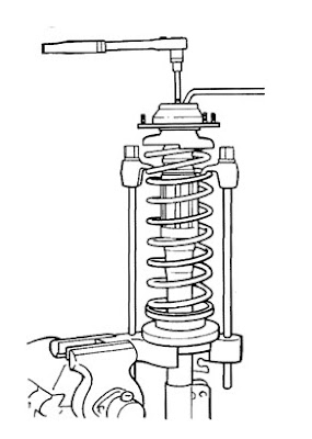
The coil springs of McPherson Struts are always under great compression, even when the unit has been removed from the car. NEVER contemplate stripping the unit unless ALL spring tension can be removed from the top plate by using spring compressors as shown. At least two compressors of the type shown must be used. Alternatively, larger tools which grip two coils in 'C' shaped brackets are available, and arguably safer. It would only take a service centre mechanic a few minutes to strip and rebuild a McPherson strut, so
unless you possess suitable facilities at home, have the job done professionally — it won't cost a lot! (Courtesy Au todata)
Torsion bars with splined ends are attached to spring plates which in turn are connected to the axle hubs. A damper connects an extension of the torsion bar housing and the axle hub. The drive shafts have universal joints (UJs) only at their inboard ends, and their angle in relation to that of the road wheel is thus constant.
To strip the suspension, chock the front wheels, slacken the hub nuts (use a six foot long lever for this) and the rear wheel nuts, raise the rear of the car and support it on axle stands placed under the rear ends of the heater channels (with wood packing). Remove the rear wheels.
Slacken off the brake adjusters and remove the hub nut, then remove the brake drum. If it sticks, try tapping it with a leather-faced mallet to free off the brake shoes. Dismantle the brakes (see appropriate section of this chapter).
Use a sharp chisel to make a mark across the trailing arm and the axle housing flange, so that they can be re­assembled in the same positions. Disconnect the damper lower end, and either swing it out of the way or undo
the top fastening.
The axle tube is secured to the swing plate by three bolts; undo these, and pull the axle tube away from the plate. Remove the torsion bar end cover plate bolts and the cover. Now for the interesting bit. The spring plate is under considerable tension when on its ledge and, when it comes free from the ledge it would fly in a downwards arc with considerably force if you were to choose to remove it by tapping it from behind. Alternatively, you could use a long lever with a cranked end to get the plate off the stop ledge and slowly release the pressure.
When the spring plate is off its ledge note its position carefully, because you'll have to get it back in exactly the same spot if you don't fancy having a lop-sided car! To raise the rear suspension ride height, incidentally, you re-fit the plate one spline further and vice-versa to lower the car. Re-fitting involves using a trolley jack under the plate to 'wind up' the torsion bar until the plate can be slipped onto its ledge. Replace the two large rubber bushes as a matter of course. To remove the torsion bars, remove the rear wings then pull the torsion bars out of their casing, noting their positioning so that they can be replaced accurately. The splines on either end of the torsion bars are of differing size, so that by moving either the inner splines one notch or the spring plate one notch, a wide variety of ride heights can be accommodated for those who like to experiment with that sort of thing.When reassembling, coat the torsion bar rubberbushes with talcum power before re-fitting. Use a trolleyjack to raise the spring plate over its stop ledge, then use long bolts to pull the torsion bar cover plate down and so force the spring plate fully home onto the torsion bar end.

Rear suspension

The two types of rear suspension fitted to Beetles are not vastly different from each other —both have torsion bar springing — but their effect on the road-holding of the cars is! Earlier swing axle cars can, when pushed to the limit, be very difficult for anyone other than the most accomplished competition driver to control. Later cars with diagonal arm suspension are far better behaved.

You can pull the torsion arm away and leave the torsion bar in place, or pull the two out together as desired. To remove the arm alone, firstly remove the bolt on the top of the torsion arm end, which locks it to the bar. (Courtesy Autodata)

The scissors type ball joint separator on the stub axle lower ball joint. Note that the nut is slackened, but left in position for the tool to bear against. If you were to remove the nut and allow the tool to bear against the thread, it would distort the thread. (Courtesy Autodata)

REPAIR AND RESTORATION


1.Brake drum 8.Taper roller bearing
2.Brake backplate assembly 9.Bearing cup
3.Stub axle assembly 10.Brake caliper
4.011 seal 11.Brake disc assembly
5.Wheel bearing nut 12.Bearing cup
6.Hub cap 13.Taper roller bearing
7.Thrust washer 14.Splash plate


The differences between the drum and disc (lower) hub
assemblies. (Courtesy Autodata)

McPherson strut suspension


Unlike torsion bar suspension, McPherson strut suspension feeds great stresses into the body shell —namely the flitch panel tops, where the top ends of the struts are located. On such cars, the panelwork around ut top mounting must be very sound.
The McPherson strut comprises a concentric coil siring and damper, combining both springing and damping roles in a simple unit, which is connected to the stub axle via a ball joint. The lower stub axle ball joint connects it to the track control arm which, in turn, Is mounted on a bracket just aft of the frame head and the movement of which is controlled by the anti-roll tabiliser) bar.
To remove the strut, chock the rear wheels, jack up the front of the car and support it on axle stands then remove the road wheels. Undo the stabiliser bar end nut on the track control arm, then remove the stabiliser bar mounting clamp nuts and detach the bar. Split the ball joint at the track control arm/stub axle, and the steering arm/stub axle. Clamp the brake hose and remove the brake pipe from the bracket on the strut.
The strut is held at the top in the flitch panel by three lock nuts; remove these —don't touch the large central nut, because this is keeping the spring compressed—and lower the strut downwards.
Don't even contemplate stripping a McPherson strut unless you have spring clamps as shown in the illustration. The coil spring is under considerable pressure and can do great damage if this pressure is not release slowly and safely. Broken or tired springs and ineffectual dampers may be replaced, but unless you have a spring compressor this work is best entrusted to a professional who, because he will not have to remove and refit the strut to the car, should not charge too much in labour.

Saturday, July 17, 2010

Wheel bearings


The damper mounts on torsion bar suspensions. Replace the !tampers if they are inefficient or are leaking. To check their ondition once removed. pull and push them through their full range of movement; any 'slack' or stiffpaints in the travel means that they have to be replaced. (Courtesy liutodata)


Wheel bearings must not be squeezed too tightly. The washer riehind the hub nut should be able to move when forced with a screwdriver, as shown here. (Courtesy Autodatn)
To adjust the wheel bearings, remove the speedometer drive and both bearing caps, slacken the lock screws and torque the clamp nuts to 15 ft lbs then slacken them until the thrust washer can just be moved. Tighten the lock screws. If you wish to replace the bearings, consult a workshop manual for details or. preferably. have the job carried out professionally.

ball joint splitter


Using a ball joint splitter to disconnect the steering arm. The type of splitter shown exerts a straight pull. and this type or the scissors type is preferable to the wedge type, because the latter can cause damage to the components. (Courtesy
Autodata)

Front suspension — torsion bar


1.Stub axle assembly

2.Eccentric bush

3.Large washerinut

4.Small washer/nut

5.Ball joint

6.Torsion bar grub screw

7.Pin

8.Upper suspension arm

9.Lower suspension arm

10.Shock absorber pin

11.Stabiliser rubber blocks

12.Metal clips

13.Stabiliser bar

14.Seal

15. Needle roller bearing

16. Metal bush

This is a very simple suspension, comprising two torsion bars per side, acting on sturdy torsion anus to which the hub assembly is bolted. The damper is attached to a special pressing which is a part of the axle assembly.
Later cars are fitted with an anti-roll bar. This simple device is in effect a 'U' shaped spring which is attached to the lower torsion arms. When one side of the suspension is compressed during cornering, the anti-roll bar flexes and compresses the suspension on the other side to a lesser extent, evening out the forces at work and preventing the car from leaning over too far.
To strip the assembly, firstly chock the rear wheels, slacken the wheel bearing nuts at the front, then raise the front of the car and support it on axle stands. Clamp the flexible brake hose as close to the brake end as possible to prevent fluid toss, then back off the adjusters and remove the brake drums, shoes, wheel bearings and brake backplates (drum brakes) or unbolt the calliper and tie it out of the way so that no strain is placed on the flexible hose (disc brakes).

Use a ball joint splitter to part the tie rod end from the steering arm and to split the ball joint in the lower suspension arm. Then remove the nut from the upper suspension arm ball joint and raise the arm using a jack and free the eccentric bush. It should now, provided the upper suspension arm is raised high enough (you may have to press the lower arm downwards slightly), he possible to remove the stub axle.
Check the condition of the ball joints and renew if necessary. The upper ball joint is fitted using a high pressure press, and it may he better to replace the upper arm complete if one can be sourced. At the top of the ball joint there should be a plastic plug which, if removed. gives access to a threaded hole. Fit a grease nipple into this and inject grease using a grease gun, stopping to move the ball joint around to help the grease penetrate properly. Fit a new plastic plug. When replacing the eccentric hush, ensure that the notched face points directly forwards.
During a full restoration, it would be usual to renew the damper units. To remove these, use a spanner on the flats of the damper shaft to hold this still whilst the top fixing nut is undone. The lower end simply unbolts. To test a damper, extend and compress it through its full range of movement; if stiff or weak points are found in the travel, or if there is any sign °clinid leakage. replace the unit.

SUSPENSION/STEERING

When a moving car hits a hump or hole in the road, a sharp force is imparted to the tyre: some of this force is absorbed by the compressed air contained within the tyre and is apparent as distortion of the tyre wall (the air in the tyre acting as a kind of spring) and the rest is imparted to the suspension system. The object of suspension is to isolate as far as possible the car chassis and body from such forces, and the suspension has two components; springs and dampers.
Like the walls of the tyres, suspension springs distort when subjected to forces and so absorb those forces. Springs which are compressed (or twisted, in the case of torsion bars) contain energy. which they try to release by re-extending. If a spring is compressed and then allowed free movement, it will extend beyond its unstressed length to a certain point (at which it still contains energy). then re-compress under the force of the remaining energy. The spring continues to extend and compress in this way until the initial energy is dissipated. This is called 'resonance'. Resonance is controlled by damping.

The effects of undamped resonance in the suspension springs of a road car would be disastrous, because every time a spring re-compressed, it would reduce the traction of its wheel, perhaps even lifting it from the road. Four wheels all shifting from full to light traction on an undamped car would reduce road-holding severely. To control the resonance of the spring, dampers (often erroneously referred to as 'shock absorbers' or 'shockers') are fitted.
When a correctly damped wheel hits a bump in the road, the spring compresses to absorb the shock (springs and not dampers are in fact shock absorbers), but the damper limits the amount of its deflection and then limits resonance, so that the spring returns to its unstressed length very quickly. This keeps the tyres in the maximum possible contact with the road.
There are essentially two types of suspension fitted to Beetles. The earlier system comprises torsion bars — bars of steel which work in effect as springs when they are twisted. Cars with this suspension are typically known as 'Torsion Bar' or 'Swing Axle' cars.
The later suspension type, fitted to the 1302 and 1303 (and 'S.) series cars, comprises McPherson strut (a coil spring with a concentric telescopic damper) suspension at the front and, although there are still torsion bars at the rear, the swing axles are replaced by double-jointed drive shafts. with diagonal arms to locate the hub. Cars fitted with this suspension are commonly referred to as 'McPherson Strut', 'Double-jointed Drive Shaft' or sometimes 'Diagonal Arm' cars.

Spring clips hold


Spring clips hold the brake line! hose union to the suspension.
Itnen refitting brake hoses on the front wheels, ensure that they cannot bend and foul the tyre at full lock. •
always wear eye protection, just in case the compressed air sprays brake fluid into the air and, for the same reason, don't work near a naked flame. Fit a clamp (a small &clamp is ideal) to retain one of the pistons, then use the air to move the other piston forwards but not out of the calliper. Open up the C-clamp to accommodate the freed piston. then use the air to drive the other out of the calliper. The first piston should now be removable by hand.
Examine the pistons and their bores for scoring and replace if necessary. Inspect the dust sealing ring and piston sealing ring for cuts or undue wear, and replace these if necessary. Before reassembly, lubricate the cylinder bores and pistons with clean brake fluid. Fit the piston sealing ring. then the piston, ensuring that the piston does not tilt within the bore. Push the piston in until approximately 'A in. remains proud, then finally fit the dust sealing ring and its retaining ring.
Occasionally, a car which has been standing idle for a time will suffer from sticking brake calliper pistons. This greatly reduces braking efficiency, and the extra load it places on the wheels with good brakes will manifest itself by those brakes locking-up under hard braking - this is especially notable when both discs are seized. Remove the pads. then examine the exposed portion of the pistons on the sticking callipers to ensure that they are not badly corroded and hence in need of replacement. If the pistons seem OK, then try replacing one pad and using a small C-clamp or a proper piston pusher to move the other piston back into the calliper. Then fit the pad to the other piston. and repeat. When both pistons are fully home. push them back out by pressing on the brake pedal. and repeat the process until the pistons are able to move properly. Check the brake fluid level frequently as you work.
One final point: when replacing the brake hoses on the front wheels following a restoration, check that they will not foul the tyres with the steering on full lock in addition to being an MOT failure point, this causes rapid wear of the brake hose.

Front brakes (disc)


Disc brakes work by pressing two friction brake pads onto a steel disc which is attached to and rotating with the road wheel. The friction caused slows the rotation of the disc and hence of the wheel. Disc brake pads are held within a casting called the calliper, within which two pistons are moved under pressure from brake fluid to push the pads against the disc.
Disc brakes are easy to service (as detailed in Chapter Three), but they are not so easy to repair, and most people seem to opt for exchange reconditioned units rather than tangle with the pistons and seals
themselves. If the pads have less than 0.08 in. of frictional material then they should be exchanged as a set.
Problems with disc brakes include excessive disc run out and general wear and tear, piston seal failure and piston corrosion. We shall deal with each in turn.
Disc run out refers to a condition where the disc is not rotating properly because it is out of balance, perhaps as a result of uneven wear or a knock. Disc run out can be checked at home by placing a fixed item (with a degree of precision) next to the disc, rotating the wheel and noting whether the disc surface remains a constant distance from the object, but it is far better to have this check carried out professionally at any service centre.
Disc wear and tear includes rusting and thinning of the steel disc through usage. scoring of the disc and colouring of the disc because it has overheated. Scoring is obvious to the eye, but in common with the other faults mentioned above, if you suspect that the discs may possess some fault then have them checked professionally.
Replacing brake pads is very quick and easy. Remove the spring clips from the retaining pins, then drift these out using a long parallel punch. Lift away the spring retainer plate, then the pads.
Corroded calliper pistons must be replaced. As the frictional material on the pads wears down, so more and more of the piston emerges from the calliper to take up the 'slack' (disc brakes are therefore self-adjusting). If the pistons are left sticking out from the body of the calliper for any length of time or in the wrong conditions — such as after driving in salty air — then the exposed portion becomes corroded. This condition is most commonly found on cars which have been standing idle for a long lime. Obviously, when new, thicker pads are eventually to be fitted then the pistons have to be firstly pressed back into the callipers; if the piston outer side is corroded then the corrosion destroys the effectiveness of the rubber sealing rings — and the lot has to be replaced.It is possible to renew calliper pistons and seals using the hydraulic system to push out the pistons, although the job is much easier if the callipers are firstly disconnected from the brake hoses and removed from the car.
Remove the pads as already described, then place a clamp on the length of flexible brake hose to minimise fluid loss. Fold back the locking tabs and remove the two hexagon headed bolts which hold the calliper assembly to the stub axle, then remove the flexible hose.
The calliper pistons may be removed by hand, although normally some assistance will be required from a low-pressure compressed air source. A foot pump will suffice, and if a compressor is to be used then turn down the pressure if possible or alternatively, take most of the air from the cylinder until the pressure is no more than 20 psi. If you try to use higher pressure air, the pistons will fly out at great speed! Whether you use a foot pump or a compressor to push out the pistons.

Popular Posts